Doing some more clean up with documentation. The TF2 Sentry Gun paper model is very under documented. Magically jumps from a base stand to a level 3 within four days.
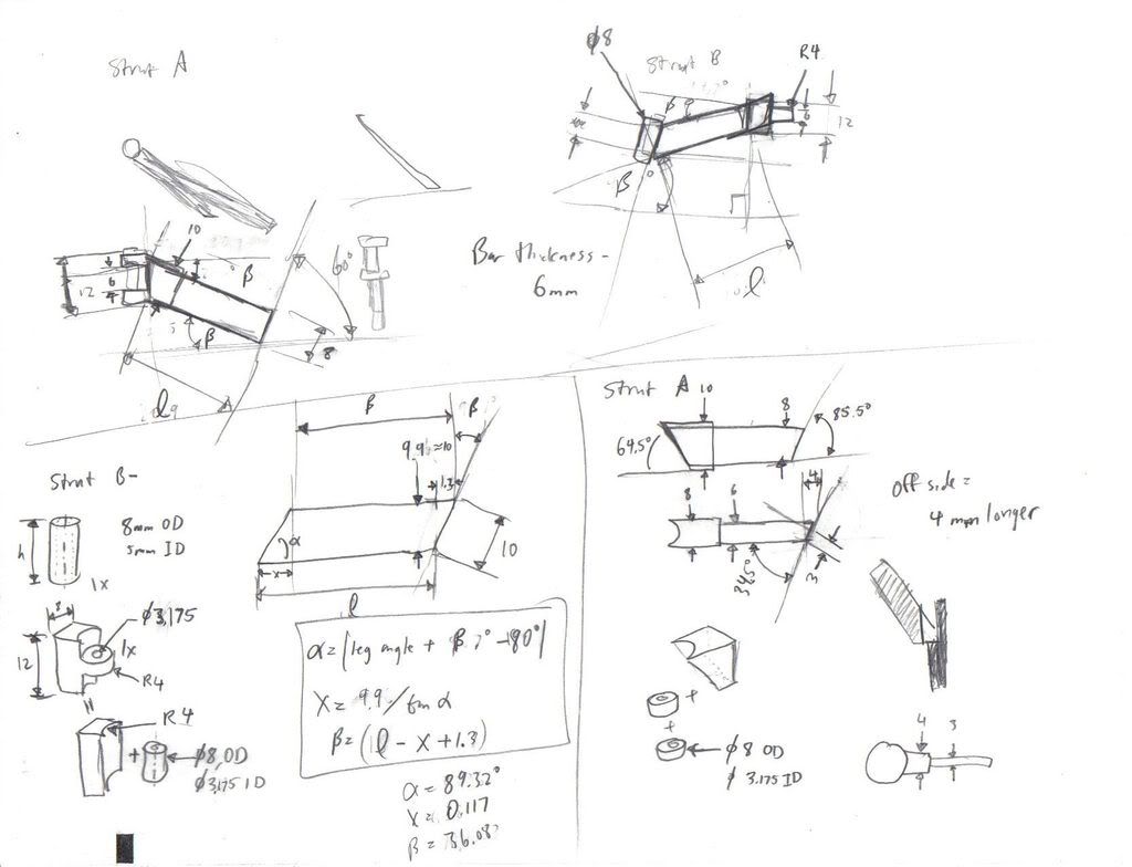
I've recently uploaded revised schematics to replace the very ineffective ones posted about two years ago. However, there's no documentation of how the parts were assembled. Time to fill in those gaps.
Building a Sentry base
The base needs to be stiff. 110lb cardstock without special treatment methods will be ineffective in supporting the loads this model will encounter. Recommend using 110lb cardstock only for tubing and using thick laminates of Magic: the Gathering to assemble every part on the base.
Magic cards offer good strength for little material. Treat them like sheet metal when building the front legs. Use thicknesses of 8 cards to create 2.5mm thick sections. The curved side frame posts were built in that manner. A thickness of 4 cards was used for minor sections like the upper parts of the front legs.
110lb cardstock is weak when used as a plane sheet, but when rolled up with or without support of a 3.175mm wooden rod, it's sturdy. The main post and rod running through it were done with both methods: using a wooden inner rod and without.
These rear legs are very troublesome. You're going to have minimal adhesive holding these parts together. Recommend making biscuits and joints to connect the sections. Super glue is recommended for these parts.
Tubes, Tubes, Tubes
A lot of the sentry will be large sections of material. The trick is to lighten up the material as best as possible. The ammo drum was built almost like a papercraft model, with lots of empty space inside. Making the drum solid would contribute excess weight to an already unstable model. Here, there's the inner drum (left), outer support drum (middle), and the outer shell (right), which is composed of a tapered cylinder. The outer shell fits alongside the outer support drum to stiffen one side, while providing the tapered shape on the other side. Magic cards were used for the flat backside, offering good planar stiffness with minimal warping.
I built the ammo drum support arm in sections. Don't do that. Build this section as stiff as possible, and out of as few pieces as possible. This part is very problematic as it supports a lot of load and will be subject to constant bending for the rest of the life of the sentry. Don't even try using 110lb cardstock without some inner support material. Stiffer the better.
The minigun assemblies are designed to spin, but also designed for weight reduction. The arch shaped supports are fleshed out using tubes on the curved ends, and troughs made of Magic cards. Tubes offer stiffness with shape, and the cards offer stiffness with flat surfaces. The only time something needs to be completely solid is for shapes 3-4mm thick or less.
For the barrels, they span a length of 40mm, but you can support them on the edges with 12-16mm of material. This lightens up the parts significantly.
For this build, I considered using pre-existing plastic tubes to minimize friction when rotating. Not a big issue in the long run since it won't see much rotation. The tubes offered strength and volume for little effort. The barrels themselves need rework, but I've drafted new plans for a stronger set in the newer plan revisions.
There's a bit of sag from the barrel weight, since rolled up 110lb cardstock is still heavy. There's little room for a counterweight, but adding more mass to the supports only loads the center mounting plate more. The goal is to minimize overall weight as well as keeping it balanced. The first objective helps with the second.
The Turret
The rocket turret is another part that requires lightening. The image above demonstrates how it was built: four tubes running along the length, with tabs on the sides to allow for a cover to be placed around it. Build this like sheet metal and not like a milled object.
These support arm parts for the turret were built light and stiff. They may appear thick, but they're mostly hollow inside.
The amount of "large mass supported by a thin strut" situations on this model are numerous. Luckily, this is the least severe of the situations. The white support base is made of several layers of 110lb cardstock, but can be done with Magic cards. The trick is to use the thickness of the material to your advantage for small details.
Wiring the Sentry
This wire assembly can be tough. You'll need to find wire with a sleeve diameter of 3mm, or make your own by rolling printer paper around some thin wires. Printer paper is soft and bends easier than 110lb cardstock when rolled. Goal is to keep the rolled thickness to a minimum. Thicker the walls, harder to bend.
Attaching the wires to the plate can be done by leaving bare wire on the ends and threading it through a sheet. Just glue another sheet to sandwich the wire ends in, and they should remain in place.
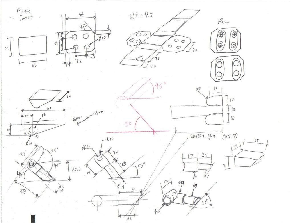
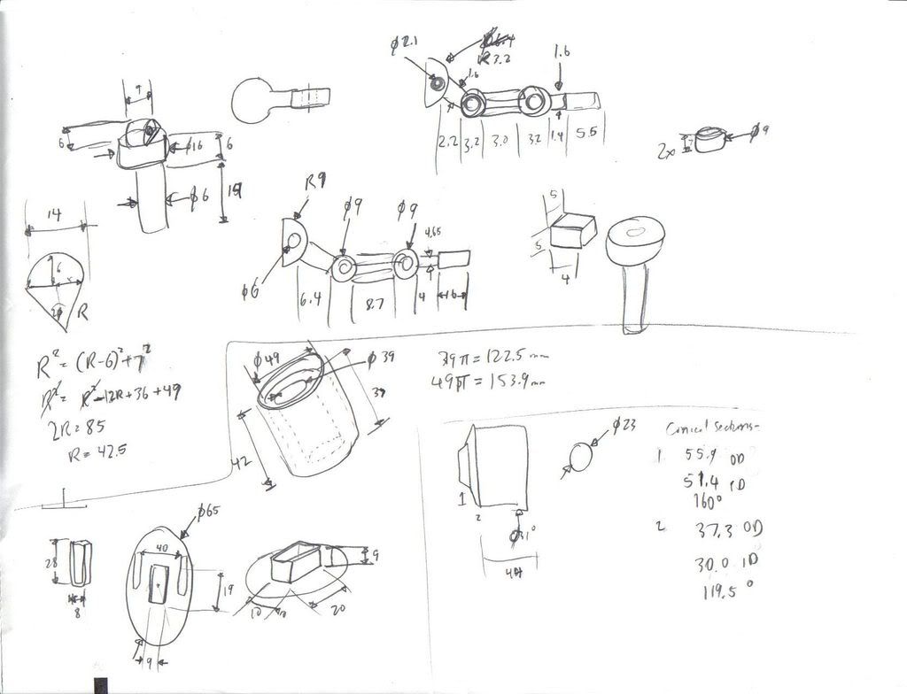
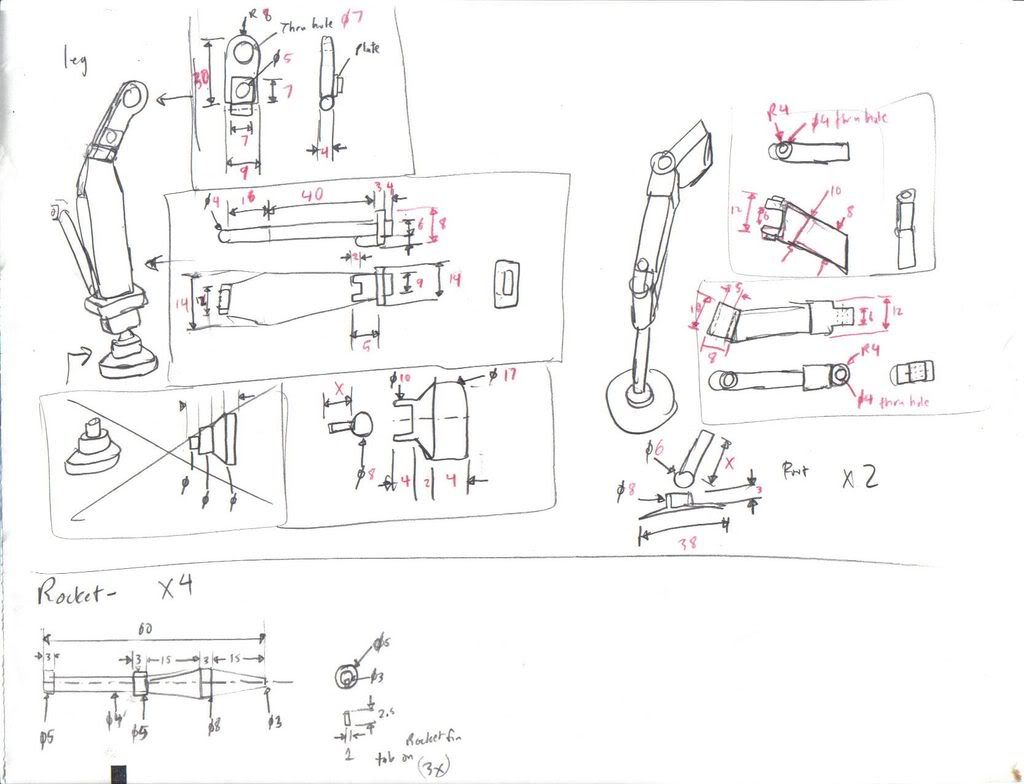
I've documented the ammo belts here, and with the rest of the new diagrams, that should cover all the miscellaneous aspects of building the sentry gun.
Now.. Just need to properly present the completed model this time around.
Showing posts with label sentry gun. Show all posts
Sunday, November 07, 2010
Saturday, November 06, 2010
Revised TF2 Sentry Gun Schematics
Reworked all the original 1:6 scale Team Fortress 2 Sentry Gun schematics I had posted previously, so that people could actually use them. I was innundated by a single comment requesting the originals be refined. Should be fully documented to the extent that you could theoretically CAD and CNC your own parts. But would you trust the accuracy of a guy hand drawing part diagrams with a ruler, protractor and a circle template guide? Probably not!
There's 8 sheets to work with, 7 of which contain dimensioned drawings for all the individual components. They're designed to take advantage of common sizes when working with paper, so you'll see a lot of 3.175mm and 6.35mm diameter holes and tubes, corresponding to a 1/8" and 1/4" hole punch. Easier than cutting a 6mm circle by hand. Best built using 110lb cardstock and Magic: the Gathering cards.
Sheet 1: Deals with the center support post.
Sheet 2: Front legs and rear supports
Sheet 3: Mounting plate for miniguns and ammo drum
Sheet 4: Ammo Drum
Sheet 5: Rocket Turret assembly
Sheet 6: Miniguns
Sheet 7: Rear legs
Sheet 8: Miscellaneous Assemblies
Next time: tips on weight reduction and building techniques using these diagrams!
Sunday, July 12, 2009
Why No One Built a 1:1 Scale Sentry Gun
Only half a year, and I've figured out all the issues that anyone trying to make a 1:1 scale exact copy of the Team fortress 2 sentry gun would have. I would like to point out first that if you do for some reason decide to build a 1:1 scale model, you're going to enjoy all the problems I've had, but on a larger scale.
This is the TF2 sentry gun in its current repaired state. I've completed all six legs and corrected for the bending issue caused by the inherent design flaw of placing a massive weight on a thin moment arm.
Figure 1: A Force Analysis
Figure 2: Support arm
I still feel that the sentry gun's legs are ridiculous. The rear legs with the large circular feet are almost purely cosmetic. They cannot bear a load well, due to the fact that they are not bearing loads axially with the leg supports, but actually causing a bending moment around their attachment point. This causes a great potential for shearing at that region. The middle two legs are actually the most important legs of the 6. They bear the greatest load being near the base of the support column, and don't have a tendency to split away from the other legs like a ladder without the center folding bracket.
What of the sentry gun's front legs? They're slightly worse than the rear legs, since they are actually held onto the main column with pin supports that are actually not rigid in position. Their structural strength lies in the support struts connecting the base of the front legs to the bottom of the support column. I would advise anyone making a 1:1 scale model to put extra consideration into the strength of the strut brackets and to actually convert the pin connections at the top of the front legs to fixed joints.
Figure 1: A Force AnalysisFigure 1 illustrates the crux of the problem with the design. What looks aesthetically pleasing in the virtual world doesn't necessarily correlate to a practical design in reality. Left, we have the side profile of the sentry gun. The middle shows what the model essentially looks like from a force analysis: two "real" ground supports, one distributed load, and one concentrated load with a pivot at the intersection of both leg supports. The right shows the resulting problem: the rear assembly starts to deflect if the support isn't properly reinforced.
Figure 2 demonstrates all the key points of interest in making the arm that supports the ammunition housing for the sentry gun. Due to the angled shape of the arm, there are multiple points of interest where the builder will need to take into account material shear and deflection. The bottom pivot pin takes on a substantial lateral load and not much concern for axial loading. Threading a rod through a circular ring solves the problem of shear located where the pin meets the support arm.
At a small scale, there are not many ways to reinforce a series of thin rods connected to cylinders. I've resorted to Loc-tite glue to be a pseudo welding compound. Works fine, but for larger versions of this model, the rods would need to be solid components with the cylindrical sections. The right half of figure 2 illustrates the only method of corrective action taken to counter the lean: reinforcing the arm base with a wooden rod. The component in that region had begun to deteriorate and delaminate. The rod strengthened the region.
Labels:
paper model,
reworked projects,
sentry gun,
structure,
Team Fortress 2
Saturday, January 10, 2009
Construction Techniques: Sentry gun ammo belts
In order to create the curved belts used for the TF2 sentry gun, I opted for a relatively simpler design of an actual flexible belt than making a solid 3D curve. I love geometry and math, but I'm not going to waste a week making a one use part that is completely unforgiving on mistakes. So, therefore, it's time to demonstrate how to make a flexible linked belt!
First off, I figured my overall length of belt would be roughly 28 cm. I chose a thickness of 4mm, width of 25mm, and a belt spacing of 6mm between links. The first thing I did was saw a lot of 25mm long sections of bamboo sticks, which were promptly glued together and wrapped in a layer of regular printer paper. These can be seen below, on the top right. I therefore had to make 28 links times 2 belts, times two rods per link. Lot of sawing.
The top left of the above image shows a pile of rectangular hollow boxes. These will be used to hide the flexible components of the belt. Each of these boxes are 26mm long, and about 8mm wide. I used 110lb cardstock for these, since strength is a factor for the outer sections.
The large grid sheet featured in the middle of the above image features eight rows of 6mm spaced boxes. These will be used to align all the parts together so there's less guessing and measuring involved later.
Here, you can see the progress of putting the parts together. From the bottom, going up, there's the gridded strips, the links being glued according to the boxes, then another layer of strips going on top to make a ladder.
The last thing to do is slip the 28 covers over the gaps in the belt. Before doing so, I posed the belt into a roughly final position. This involves pinching the belt supports together so they start to curve. It's harder to bend the belt into odd curves later when the belt covers are all on. After that, all that's left is to slide each part onto the belt and position them. A bit of glue is needed to hold them in place, but you also want movement too. I glued one edge of the rectangular box to the belt itself, so the other is free to move.
Here's a finished shot of the belts. There's realistically no practical reason why you would need to make these for another project, since there are few things that need covered ammo belt feeds. However, I hope that by recording my processes, you find some inspiration in solving odd problems with something interesting.
First off, I figured my overall length of belt would be roughly 28 cm. I chose a thickness of 4mm, width of 25mm, and a belt spacing of 6mm between links. The first thing I did was saw a lot of 25mm long sections of bamboo sticks, which were promptly glued together and wrapped in a layer of regular printer paper. These can be seen below, on the top right. I therefore had to make 28 links times 2 belts, times two rods per link. Lot of sawing.
The large grid sheet featured in the middle of the above image features eight rows of 6mm spaced boxes. These will be used to align all the parts together so there's less guessing and measuring involved later.
Labels:
Build progress,
paper model,
sentry gun,
Team Fortress 2
Friday, January 02, 2009
Source Material Design Directions for the Team Fortress 2 Sentry Gun
I've been mulling over the past week or so wondering what was Valve thinking when they were designing the sentry gun model. The stand isn't really proper, there's redundant supports, and the ammo feed housing is ill supported by a thin network of struts. However, I've come across something that probably was part of the source inspiration behind the design of the sentry gun.
The Maxim MG-08. The significant difference between the stylized counterpart on the top and the real world World War I sled mount is the fact that the real one doesn't fall over. There's a lot more mass, and locking grooves for positioning the foreward legs. Apparently, the design of the Maxim MG-08 mount is to serve as a sled for pulling it along, which explains the curved form on the front, and the near negligible legs on the back. Quite amusing that the Engineer chose an antiquated German machine gun stand for such a sophisticated mechanism.
The Maxim MG-08. The significant difference between the stylized counterpart on the top and the real world World War I sled mount is the fact that the real one doesn't fall over. There's a lot more mass, and locking grooves for positioning the foreward legs. Apparently, the design of the Maxim MG-08 mount is to serve as a sled for pulling it along, which explains the curved form on the front, and the near negligible legs on the back. Quite amusing that the Engineer chose an antiquated German machine gun stand for such a sophisticated mechanism.Tuesday, December 30, 2008
TF2 Level 3 Sentry Gun Paper Model Reference Dump
I do, however, have the eight sheets of plans and diagrams I used to construct this. Here they are, presented in no special order. These eight sheets, along with a few images of the sentry gun, are all I used to build this. No CAD or game model rips involved.
Page 1 (References the construction of the rear, angled leg struts)
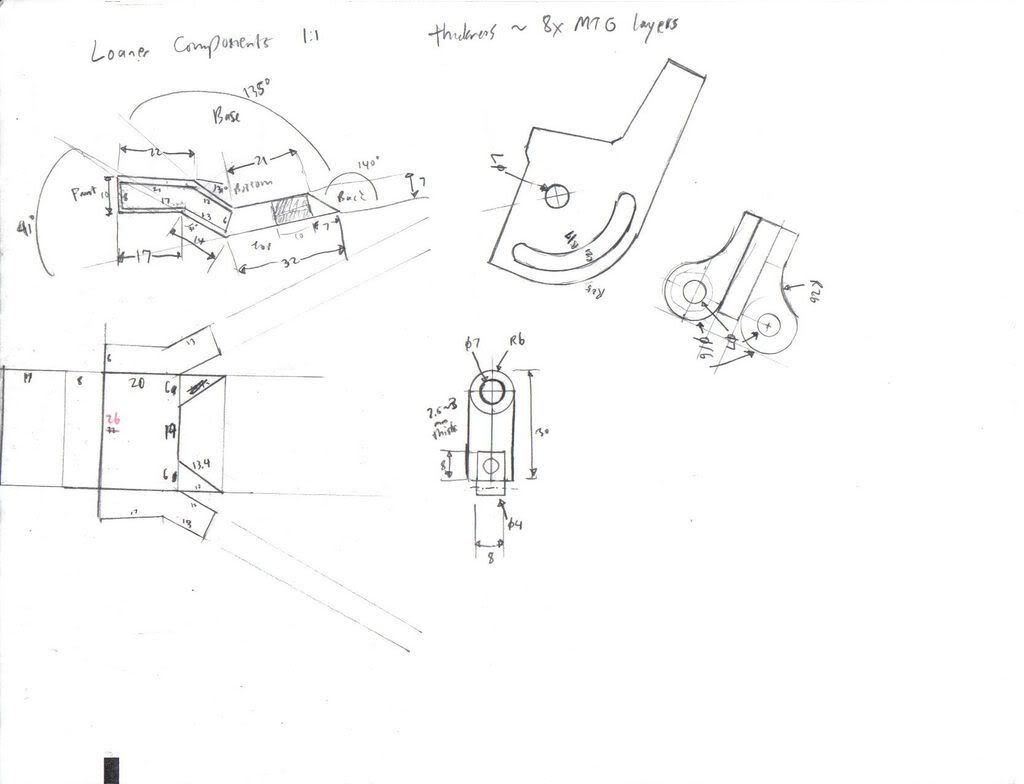
Page 2 (References the parts borrowed from the two source sentry models)
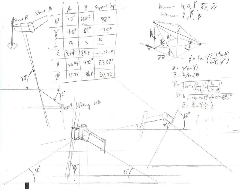
Page 3 (Calculations of strut length, angle of attachment, and angle of orientation)
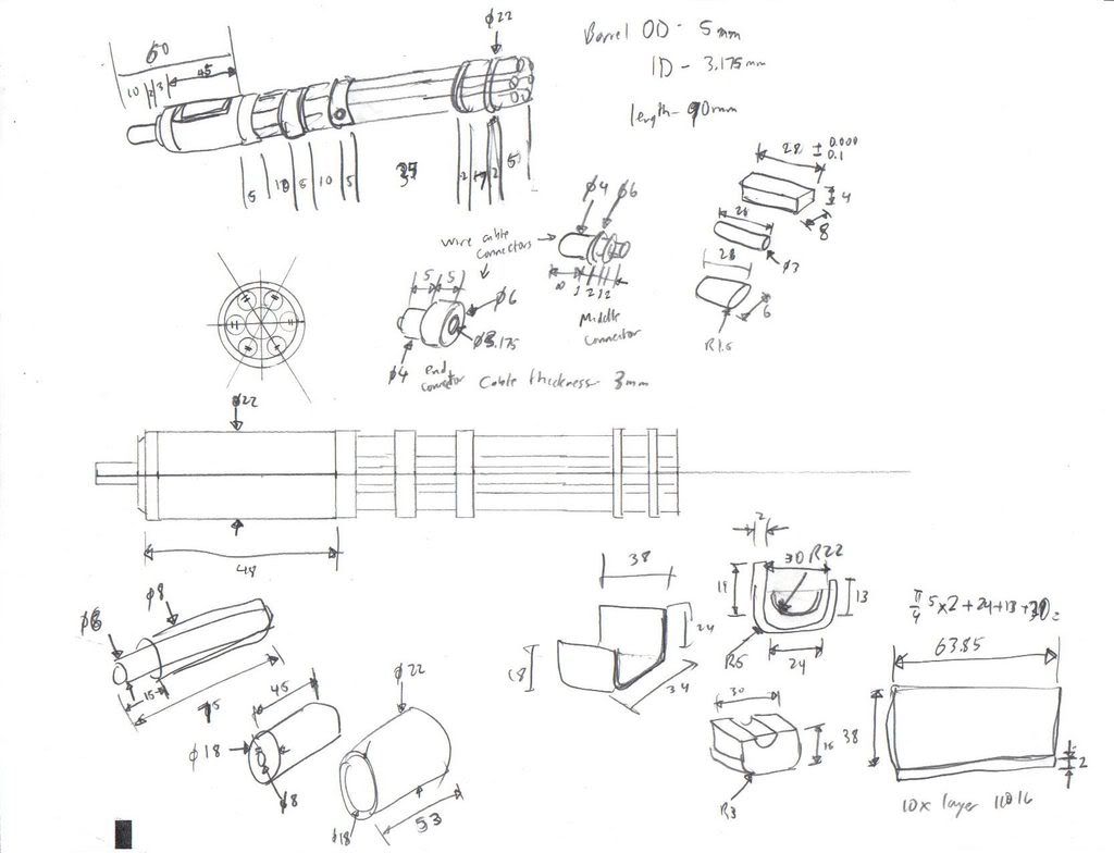
Page 4 (Minigun assembly)
Page 5 (Preliminary draft of part dimensions)
Page 6 (Turret design and support shaft)
Page 7 (Ammo housing and support struts)
Page 8 (Preliminary draft for front and rear leg; rocket cross section) (EDIT: corrected bad link)
There's a few parts that I have not documented since they were made on the fly. The front leg struts to the center shaft, wires, electrical plate, and miscellaneous decorative fasteners are unknown. These can be provided on request.
I'll be documenting individual components in detail over the course of the next few weeks, highlighting various construction decisions used. Many of the applications here can be useful for future project reference.
Monday, December 29, 2008
This (last) Week(end)'s Project: Building a Sentry Gun
It has been about 5-6 days after starting construction of the Team Fortress 2 Level 3 Sentry Gun. I've consumed a total of 38 Magic: the Gathering cards (which I've finished all the structural aspects with) and about 10-20 sheets of 110lb Cardstock (I've lost count). I've also used about 17 bamboo skewers. I have reached 8 pages of documentation covering the design and construction of various components. This paper model outclasses the minigun "Sasha" in terms of complexity and weight and outnumbers it in unique components needed for construction. I dare say, it uses more Magic: the Gathering cards to construct than Lia.


This stage currently is missing the following details:
Electrical wires
End caps for holding the rotating minigun barrel assemblies to the housings
Middle redundant feet supports
Rockets (x4)
Ammunition feed belts
Misc decorative fasteners and bolt heads
I'll elaborate on the finer details of the construction after I finish this task. So far, in order to properly assemble the sentry support, I had to glue down parts now. Unfortunately, if I do that now, painting would be difficult to do due to the crevices and small clearances. Therefore, my original plan of leaving it unpainted to show off the materials used in the construction fizzled. Right now, there's a blue wire holding the front legs/support column to the frame. There's a very logical reason for this: the design I've based this off of isn't feasible in real life.
The center support column is composed of a cross shaped piping piece, with two ends feeding into the frame. These parts also conveniently form the pivot for the front legs, which are attached to the middle post by the lower struts. There's nothing holding them to the curved frame, so when weight is applied to the post, it creates a moment on a non fully constrained support, causing slip. Think of a board resting on wall. Apply a load to the top, and the bottom will slide out, causing the ladder to fall. I'll do a proper over-analysis of the sentry design later as well, once the zeal of completing this monstrosity ends.
Electrical wires
End caps for holding the rotating minigun barrel assemblies to the housings
Middle redundant feet supports
Rockets (x4)
Ammunition feed belts
Misc decorative fasteners and bolt heads
I'll elaborate on the finer details of the construction after I finish this task. So far, in order to properly assemble the sentry support, I had to glue down parts now. Unfortunately, if I do that now, painting would be difficult to do due to the crevices and small clearances. Therefore, my original plan of leaving it unpainted to show off the materials used in the construction fizzled. Right now, there's a blue wire holding the front legs/support column to the frame. There's a very logical reason for this: the design I've based this off of isn't feasible in real life.
The center support column is composed of a cross shaped piping piece, with two ends feeding into the frame. These parts also conveniently form the pivot for the front legs, which are attached to the middle post by the lower struts. There's nothing holding them to the curved frame, so when weight is applied to the post, it creates a moment on a non fully constrained support, causing slip. Think of a board resting on wall. Apply a load to the top, and the bottom will slide out, causing the ladder to fall. I'll do a proper over-analysis of the sentry design later as well, once the zeal of completing this monstrosity ends.
Thursday, December 25, 2008
This Week's Project: Buildin' A Sentry!
So far, there have been two papercraft Team Fortress 2 sentry gun models. However, both are level 1 sentries. highwaychile.net's model can be found floating around other sites. raven-age.org's can be found here.
EDIT: highwaychile.net's model is no longer available. -J.Norad
I'll be using both as a reference for the support structure for my level 3 sentry gun model. In theory, it's merely an addition to the pre-existing models, so it'll be easy, no?
I personally liked highwaychile's version more, but both are quite lacking in the extra legs department. For reference, I'm making them in 1:6 scale to the best of my ability, and the other two can be used at 1:6 scale if scaled to 119% of the original size.
For this attempt, I'll be using my staple, the Magic: the Gathering card. I'm attempting some new methods this time that I'd like to comment on. Typically, I've been cutting and gluing each layer one at a time for the sole reason of not being able to cut through eight layers of cards glued together with the consistency of a thin wood board. However, I now have a Dremel rotary cutting tool.
My experiences have mixed results. Using a Dremel's circular cutting disc on a laminated stack of cards causes two severe health hazards. It first off, burns part of the card, creating some smoke and fumes. Second, paper is made from wood, and well, cutting wood makes a lot of sawdust. I ended up with a nice cloud of brown powder everywhere. Cutting the cards works best on the max setting, otherwise, the cutting disc grabs onto the material and starts slowing down.
Finer details were also problematic. I don't have the luxury of having the 1/4" drill accessory, so I had to improvise using the 1/8" drill bit, an X-acto knife, and a lot of stabbing. However, after about eight hours of apathy, here's the results.
Eight layers of Magic cards creates a thickness of roughly 3mm, a fact that I will exploit in designing and constructing individual elements. More progress pictures as they come, and eventually the diagrams for each part will follow.
EDIT: highwaychile.net's model is no longer available. -J.Norad
I'll be using both as a reference for the support structure for my level 3 sentry gun model. In theory, it's merely an addition to the pre-existing models, so it'll be easy, no?I personally liked highwaychile's version more, but both are quite lacking in the extra legs department. For reference, I'm making them in 1:6 scale to the best of my ability, and the other two can be used at 1:6 scale if scaled to 119% of the original size.
For this attempt, I'll be using my staple, the Magic: the Gathering card. I'm attempting some new methods this time that I'd like to comment on. Typically, I've been cutting and gluing each layer one at a time for the sole reason of not being able to cut through eight layers of cards glued together with the consistency of a thin wood board. However, I now have a Dremel rotary cutting tool.
My experiences have mixed results. Using a Dremel's circular cutting disc on a laminated stack of cards causes two severe health hazards. It first off, burns part of the card, creating some smoke and fumes. Second, paper is made from wood, and well, cutting wood makes a lot of sawdust. I ended up with a nice cloud of brown powder everywhere. Cutting the cards works best on the max setting, otherwise, the cutting disc grabs onto the material and starts slowing down.
Finer details were also problematic. I don't have the luxury of having the 1/4" drill accessory, so I had to improvise using the 1/8" drill bit, an X-acto knife, and a lot of stabbing. However, after about eight hours of apathy, here's the results.
Labels:
Build progress,
paper model,
sentry gun,
Team Fortress 2
Subscribe to:
Posts (Atom)